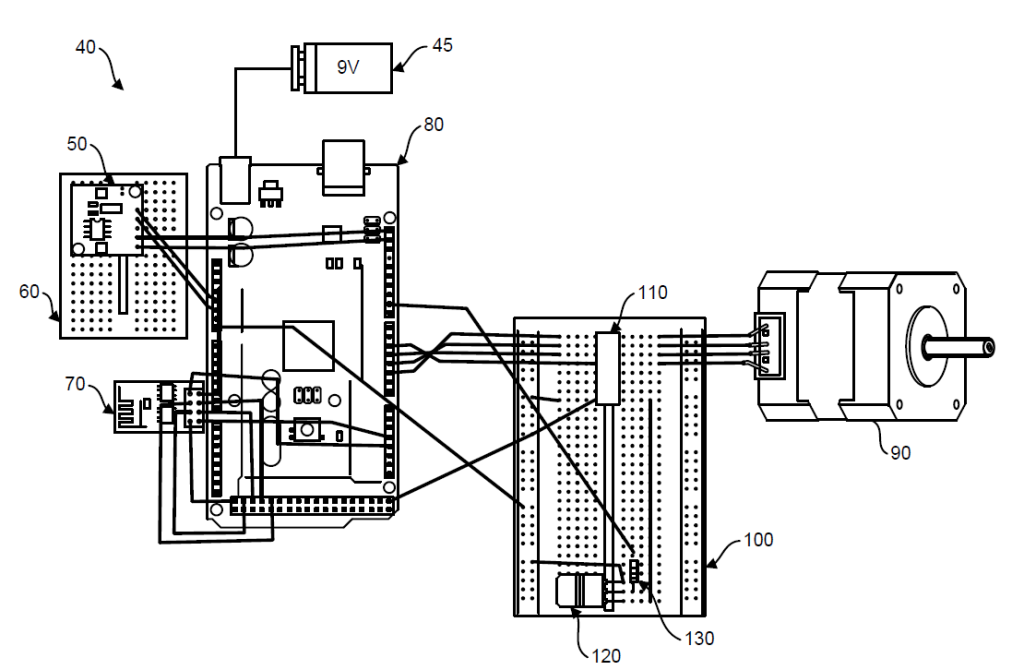
the electronic circuit diagram of one module/unit of the pill dispenser system. The operation of the system is controlled by the Arduino Mega board. The Arduino Mega can be replaced by a smaller microchip to make the system size small without compromising the function of the system. A real time clock module is connected to the Arduino Mega board via a breadboard that provides accurate time and date. A WiFi module is connected to the Arduino Mega board to connect to the Android application on a cell/mobile phone. The touchscreen display is directly connected, not shown here, to the Arduino Mega board when the data is directly fed instead of the cell/mobile phone via the Wi- Fi module wirelessly. A stepper motor is connected to the Arduino Mega board via a breadboard to control the rotation of the wheel as shown in FIG. 4, FIG. 5 and FIG. 8. The rotation of the stepper motor is controlled by a Darlington array which is connected to the motor via the breadboard. The breadboard allows to make temporary connections between electronic components without soldering. A power transistor controls high currents and voltages, and is provided to amplify or switch electronic signals. The power transistor on a breadboard allows to create circuits that control motors, LEDs, buzzers, and other devices that require more power than a typical microcontroller can provide. Three pins of the power transistor are connected to the breadboard. The resistor is used to provide the resistance to high voltage power and is used to protect LEDs, divide voltage, and provide precise current values for circuits. A LED directly connected to 9V power supply will burn out quickly. The resister limits the current flowing through the LED so that the LED is not burnt out. A 9V battery powers the system. Alternately, the system can also be powered by direct supply of power via an electrical outlet.